
给EM2040D加装了POSMV以后,需要校准对POS姿态传感器进行角度校正。使用SIS软件的校准模块,发现无法加载校准测线文件,对比了SIS的说明,发现与帮助说明唯一不同的是,geographical window没有地形影像只有航迹。

SIS经常不能实时加载地形影像,已经习以为常了。由于测量校准测线没有新建survey项目,还在之前的项目里,这时想到可以用校准测线的RAW文件重建survey项目和地形影像。重建完成以后,想打开survey项目,却发现如下错误:

问了张工这个问题,他说gridengine没有正常启动,但是gridengine没有一个EXE,只有一个geserver的console后台控制着gridengine,但是它与SIS同时开启,没有关闭。看了右上角的build information,提示gridengine没有Response,但是没有途径重启,真实令人非常无语,张工说这个错误经常发生,放弃吧,另外想辙。

还有一个办法通过CARIS进行校准,对于all格式的raw数据,船型文件都设置成0,与Reson 7125的方法不一样。Reson 7125需要重建全部位置和角度等全部安装参数,用CAIS校准好办,但是all数据直接得到的是最终水深。
手上还有一个软件,Qimera,读入all数据,发现这个软件非常不错,将EM2040D用到的所有的定位和姿态设备的位置和角度偏移都还原了,比如EM2040D使用了2套定位和姿态系统,测量时激活了POSMV但也记录了HYDRINS的数据。Qimer读入all数据以后,定位出现了POS1,POS2和POS3,显示测量使用POS3,姿态出现了MRU1和MRU2,显示测量使用MRU2,POS和MRU的偏移量与SIS软件一致。
随后,利用Qimera进行了校准,再将校准值输入SIS软件。这里,有1个小问题,就是正负值的问题,因为有HYDRINS作为参考,能输入正确的校准值,如果没有参考,怎么办呢?
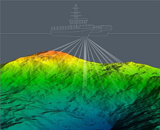
从SIS软件的帮助,可以知道SIS的坐标系统如下:

从图中可以看出,向前为正,向右为正,向下为正。

从坐标轴前面向后看,逆时针为正;例如,从X轴前向后看,逆时针为正,就是左舷上翘为正值,从Y轴前向后看,就是前翘为正值,从下往上看,偏右为正。
这样就可以根据校准值的方向,确定校准值的正负号。
EM2040D应对旁边SES2000的干扰问题
船底固定安装时,为节约空间,会将EM2040D和SES2000装在一起,按照常规应该装声学同步器,但是影响这两个设备的工作效率,我们的目标是既要相互之间干扰少又要2台设备的工作效率,浅水工作一般不安装声学同步器。SIS提供抗干扰的选项,但是效果不明显,必须多种手段齐下,比如说SES2000的频率是3KHZ至10KHZ,SIS可以提供200KHZ、300KHZ和400KHZ,那么SIS选择400KHZ,频率相差越大,干扰越小,Defect mode选择WaterWay比Normal更好,下面是选择300KHZ和400KHZ,WaterWay的效果对比图:


Ping mode: This parameter defines the operational frequency of the multibeam echo
sounder. Depending on your application you can select frequencies:
• 200 kHz – for deeper waters
• 300 kHz– for normal operation
• 400 kHz – for very high resolution inspection
• 300 kHz: Three transmit sectors are used per swath. Different frequencies are used
to separate the sectors. With short pulse length each sector needs a large bandwidth.
This means that frequencies used may be e.g. 260, 290 and 320 kHz. With long
pulses a reduced band width is required. To extend the coverage, low frequencies are
selected, like 270, 275 and 280 kHz. For each mode and pulse length the system is
tailored for optimum use of the bandwidth.
• 200 kHz: At 200 kHz the transmit sectors are wider, so only two sectors are needed
per swath. Compared to 300 kHz mode the maximum range is increased caused by
lower attenuation in the water, whilst the beam widths are increased by a factor of 1.5.
• 400 kHz: Due to the high frequency the beam opening angles becomes narrower, and
the range coverage is decreased, compared to 300 kHz. Shorter transmit pulses are
used. This requires correspondingly higher bandwidth and gives increased resolution.
Detector mode: Select detector mode to optimize the systems ability to recognize the
bottom, wreck, structures, etc., depending on water condition. Select from:
• Normal: The normal bottom detection mode
• Waterway: Suitable for shallow channels and rivers
• Tracking: A general shallow water mode for tracking of targets and sudden depth
changes
• Minimum depth: Designed for detecting wrecks etc.
The Waterway, Tracking and Minimum depth modes are mainly intended for use in
shallow waters. In shallow waters special TVG may improve the performance. A
tracking routine is used instead of the ping-ping filter. This means that the bottom
tracking does not depend that much on the previous pings and will easier track sudden
depth changes. Range gate, based on previous pings, still limits the search.

发表评论: